
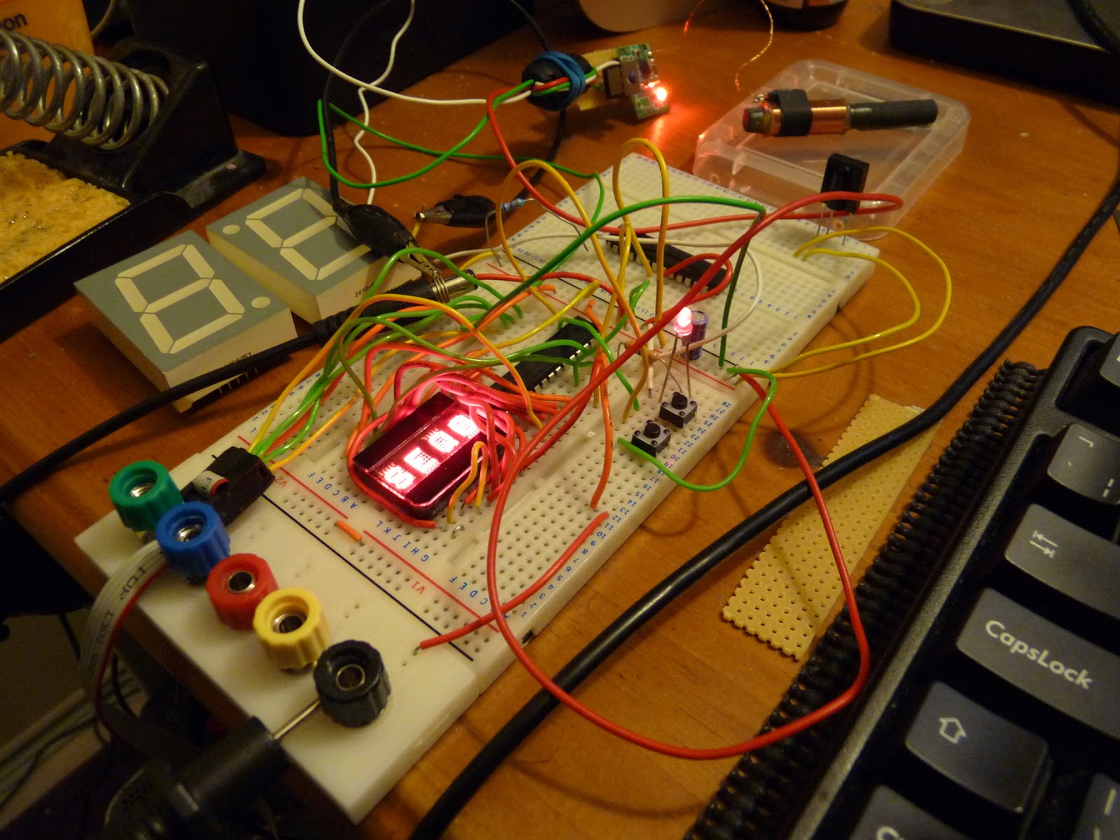
 There's a project on the back burner at London Hackspace to make a better alarm clock. One of the first things we need for this is a way to figure out the current time, instead of bothering the user to set it.
There are a number of ways to obtain this automatically. Both GPS and GSM could be used, and in most houses, WiFi could be used to connect to a time server. DAB is also a possibility in Europe. None of these are particularly cheap though. It would be difficult to get a receiver working for under 20 pounds with any of these methods.
The National Physical Laboratory transmits a time signal by low frequency radio from Cumbria. This is also known as MSF from its old radio call sign. Similar services exist in Germany and the USA, at least. A receiver can be had for 9 pounds from PV Electronics, however, using it hasn't been particularly easy. The signal coming from the module is TTL level, but in my experience, very noisy in the time domain. The signal I got on the first try looked more like this:

Eurgh. Some of this is due to the power supply; the module needs a very clean power supply and it took me a long time to get any sensible data while running from a mains supply. Giving the Symtrik module its own linear regulator, some big capacitors and a choke seem to have improved it. The orientation and position of the antenna is also important; I've noticed that it will produce garbage if it's too close even to an AVR running at 1MHz. LCD monitors in particular seem to drive it crazy.
We could use analogue means to try and get an average value over the expected length of a pulse, or sample it several times and take the most common value. Those are approaches I might go back to, but for now, I'm sampling it just once in the middle of the pulse.
The MSF Specification is pleasantly simple. The most important thing to recognise is the minute marker, since all the remaining data frames' meaning is dependent on their sequence after it. If you treat all the frames as 4-bit frames, sampled at 150, 250, 350 and 450ms from the first rising edge, then the minute frame is all 1s, while the other frames always look like XX00. By using four samples it's unlikely to detect a false minute marker, and it's better to miss a minute marker than detect one when there wasn't one. Note that the Symtrik module outputs an inverted signal, which is why the diagram above is upside down compared with NPL's diagrams.
Unfortunately the signal only has four parity bits for error detection, and only one of those covers the hour and minute information that's really interesting to us. So the best resort we have is to collect data over several minutes, and compare them until we get a sequence of minutes which give us enough confidence to change our current idea of the time.
This means we now maintain three notions of time:
| Display Minutes | Expected Minutes | Radio Minutes |
| Display Hours | Expected Hours | Radio Hours |
Display time is what we currently display and consider the current time to be; this isn't something we want to change lightly and of course increments by itself. With a crystal oscillator we can expect an AVR to keep good time for months.
Expected time is what we'd expect the next radio frame to say; this also needs to be incremented automatically when we don't get a sensible radio time. Radio time is the time read from the radio this minute. At the end of the minute it's compared with the (pre-incremented) expected time and if it matches, we increment a sequence counter. If it doesn't match, that counter is reset and the radio time is incremented and becomes the expected time for the next frame.
Once we get a high enough sequence (at the moment, 3 agreeing minutes) we can use that to set the display time. If we don't have a current display time (just after power-on, for example) then the standards can be lower.
I'll provide some C code for the AVR when I have it working well. Debugging is an annoyingly slow process, being locked to the minute cycles of the NPL signal.


