No longer updated!
My blogspot site is no longer updated. Most of the posts here are archived at www.srimech.com along with new content.
Thursday, 13 June 2013
Grue detection t-shirts
In low light conditions the t-shirt looks like this. Find a light source quickly.
I had this prototype made at spreadshirt.co.uk; in case it's not obvious, it's a combination of reflective and glow-in-the-dark vinyl print. Unfortunately, spreadshirt can't guarantee the alignment of these two print materials, otherwise I'd be offering a link to buy these essential pieces of safety equipment.
Thursday, 31 January 2013
Reimplementing TinyHack in PyGame
It's a reimplementation rather than a port; Rob did provide the source, but it's in Flash format which I've no idea how to read. The 'artwork', levels and sounds are remade from scratch, using SFXR again for the latter. It's stripped down somewhat - the world is smaller, only having three 'dungeons', there's no magic, and no village, although the pub still exists.
Behind the scenes, there are two main global stores of information in the game. There's a large map, a 2D array of integers, which changes occasionally (squares which represent gold or items are replaced with empty squares when the player moves over them). The second part is a 1D array of 'Entity' objects which contains the mobile things; the player and any enemies. Entities have an x and y position and HP (health) as well as a few other bits. To make things simple, the player is always at index 0 in the entity array. To draw the screen, it's only necessary to draw the map around the player and then the entities. Timing is basic; the game waits for a keystroke to do a player move, and then does an enemy move if the player did actually move anywhere. Enemies have very basic AI, and will just move towards the player if they can. When trying to move in any direction, the game needs to check both the map and the entity list for space. If there's an entity blocking the target square, the entity may attack the target. Enemies are marked as one team which is different to the player, so they won't attack each other. Finally, the player has the extra option of moving into 'teleporters' which are the red squares on the map.
Items and gold aren't part of the movement routine, but are checked for after moving. Gold just disappears and a counter is incremented. Items need to do different things, so there's a static Python dictionary which maps coordinates of items to types. (39,14) is the shield, for example. A similar dictionary maps teleporters to their destinations. There are also some special teleporters, such as the pub and the jetty, which are marked as special by having a destination x coordinate of 0. The y coordinate in these is an action index which is taken instead of moving the player. 1 is the pub which restores the player's health and 2 is the jetty which ends the game.
The map and teleporter/object data could be coded directly in Python, however it's a lot more convenient to do it in Tiled. As well as making the base map, it's also possible to use Tiled to specify the teleporter relationships and other bits using an object layer. The collectible items, for example, are marked by small objects on the map with the 'item' property set to either 'hp', 'sword' or 'boat'. The code to read this data out of Tiled's XML and into Python structures is in the separate file 'tilereader.py'.
TinyHack removed a lot of common Roguelike features to make it work in a simple graphical environment: Lighting, line of sight, decent enemy AI, inventory, statistics, skills, fine-grained turn timing and random level creation are all missing. It's still a fun game though. As I said, MicroHack is a starting point, and I'd like to add to it. The question is, which of the missing features are actually important?
As usual, the code is in github at https://github.com/jmacarthur/2dgames, in the 'microhack' directory.
Friday, 2 November 2012
Error correction of the NPL time signal
There's a project on the back burner at London Hackspace to make a better alarm clock. One of the first things we need for this is a way to figure out the current time, instead of bothering the user to set it.There are a number of ways to obtain this automatically. Both GPS and GSM could be used, and in most houses, WiFi could be used to connect to a time server. DAB is also a possibility in Europe. None of these are particularly cheap though. It would be difficult to get a receiver working for under 20 pounds with any of these methods.
The National Physical Laboratory transmits a time signal by low frequency radio from Cumbria. This is also known as MSF from its old radio call sign. Similar services exist in Germany and the USA, at least. A receiver can be had for 9 pounds from PV Electronics, however, using it hasn't been particularly easy. The signal coming from the module is TTL level, but in my experience, very noisy in the time domain. The signal I got on the first try looked more like this:
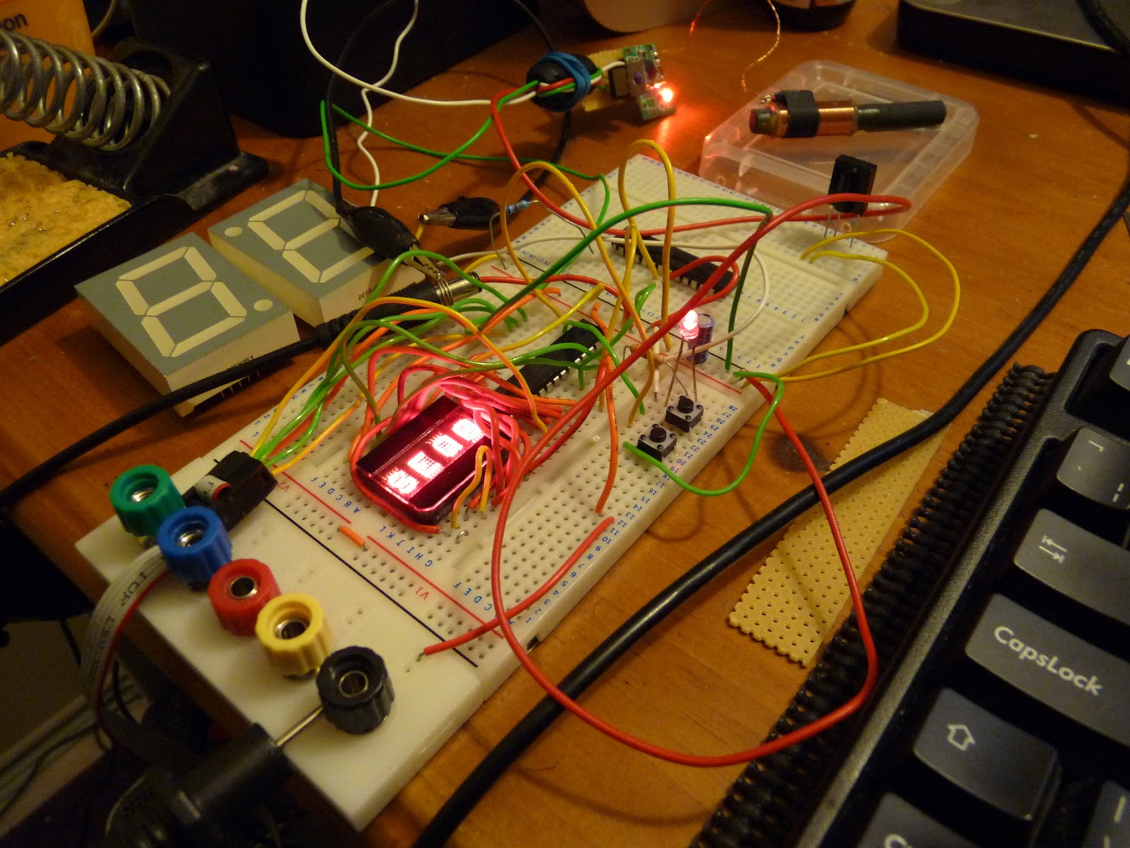
Eurgh. Some of this is due to the power supply; the module needs a very clean power supply and it took me a long time to get any sensible data while running from a mains supply. Giving the Symtrik module its own linear regulator, some big capacitors and a choke seem to have improved it. The orientation and position of the antenna is also important; I've noticed that it will produce garbage if it's too close even to an AVR running at 1MHz. LCD monitors in particular seem to drive it crazy.
We could use analogue means to try and get an average value over the expected length of a pulse, or sample it several times and take the most common value. Those are approaches I might go back to, but for now, I'm sampling it just once in the middle of the pulse.
The MSF Specification is pleasantly simple. The most important thing to recognise is the minute marker, since all the remaining data frames' meaning is dependent on their sequence after it. If you treat all the frames as 4-bit frames, sampled at 150, 250, 350 and 450ms from the first rising edge, then the minute frame is all 1s, while the other frames always look like XX00. By using four samples it's unlikely to detect a false minute marker, and it's better to miss a minute marker than detect one when there wasn't one. Note that the Symtrik module outputs an inverted signal, which is why the diagram above is upside down compared with NPL's diagrams.
Unfortunately the signal only has four parity bits for error detection, and only one of those covers the hour and minute information that's really interesting to us. So the best resort we have is to collect data over several minutes, and compare them until we get a sequence of minutes which give us enough confidence to change our current idea of the time.
This means we now maintain three notions of time:
| Display Minutes | Expected Minutes | Radio Minutes |
| Display Hours | Expected Hours | Radio Hours |
Sunday, 12 August 2012
Simple, headphone-controlled phone robot
TL;DR: The headphone socket on some Android phones is a good enough signal generator to control servo motors almost directly.I had an idea recently that servo motors could be driven directly from the headphone socket on an Android mobile phone. I was probably subconsciously remembering this old this old Hackaday link; anyway, it turns out that it's very easy to do.
Servo motors expect a square pulse of 5V of between 1 and 2 milliseconds, usually once every 20 milliseconds. 1 millisecond is canonically fully left, 2 is fully right, and 1.5ms is in the centre, although there is quite a lot of variation. So, I created a suitable square wave by hand in Audacity, saved it as a .WAV file and played it back on my phone's default media player app, while looking at the headphone levels on an oscilloscope. There are lots of reasons to not expect a square wave to come out of an audio amplifier, but the result was actually a very faithful reproduction of my square wave. The maximum voltage I could get out of it was just under one volt, not enough to drive a servo directly, but enough to turn a transistor on. On both the phones I've tried - a HTC Hero (G2) and Desire C - the voltage out of the headphone port is negative with respect to the value in the wave file, so the wave file needs to be between 0 (off) and -32768 (pulses) for a 16-bit sample. As well as playing back standard audio files, it's pretty easy to generate audio on the fly, so you can control servos direct from your application.
Here's my circuit diagram (I've only done shown one channel - it's identical for both). I'm not suggesting you try this - it might break your phone in some way I haven't thought of. This is just to show what I've done.
I've used two bog standard NPN transistors in my circuit; the second is acting as a second inverter as the first one inverts the signal once. I think it should be possible to do this with one transistor, and an inverted wave file (using 0 as the pulses and -32768 the remainder of the time) but it hasn't worked when I've tried it and I don't have ready access to an oscilloscope to figure out why.
Nonetheless, this is a very cheap way of controlling servos from a mobile phone and I would like to find out whether it works on more Android devices. The transistors cost about £5 for a hundred and there's just another 3 resistors per channel to make it work. It is limited to two servos, so if you want more connectivity, you'll probably be after more powerful devices like the IOIO.
This idea gets more useful when you use continuous rotation servos. Here's a video of my old phone running two such servos with wheels attached. Even old Android phones have cameras, accelerometers and wifi, which makes them great brains for simple robots. Running two servos from the headphone socket gives them very cheap mobility.
PS. I've since become aware of http://www.gluemotor.com/ which is a very similar device. They don't have any transistors; but use a capacitor on each channel to provide AC coupling. I couldn't get this to work when I tried it with my Android phone - maybe with more experimentation. Still, nice work.
Two more demos: Meteor Miner and Platformatic
Fuel is limited and ore makes you heavier. You can escape the meteor with just one tonne of ore, but the goal is to recover all of it.
This is the first game I've done with sound, although on all the platforms I've tried (Ubuntu, Windows 7 and Android) the sound suffers from an annoying latency. The game works well with the PyGame subset for Android but as PyGame doesn't handle multi-touch devices yet, I can't emulate the buttons on a touchscreen, so it will only be playable with a keyboard.
Platformatic is a puzzle game which looks like a platformer; rather than asking the player to time jumps exactly, it asks him or her to place instruction symbols onto the screen, which the character will follow when it treads on them. This partly came out of my frustration with platform games which require you to make a long sequence of carefully timed actions, often repeating the first ones hundreds of times until you finally get the last one correct.I'm not particularly pleased with either of these games, but I've forced myself to bring them to a point at which I can publish them, as I otherwise tend to abandon old projects while half-finished and start on new ones.
Both games are available from my 2dgames repository on github and are MIT licenced: https://github.com/jmacarthur/2dgames. As before you'll need PyGame to play them; as I get better at creating games, I'll consider packaging some of them up or porting them so they can be played more easily.
Wednesday, 18 July 2012
Investigating Raspberry Pi performance problems
I bought a Raspberry Pi some time ago and have been trying to run some of my PyGame games on it. I'm going to describe one performance issue I've seen with it. This isn't a criticism of the board in general, which I still think is excellent for the price.I wanted to show something off at the Raspberry Jam last weekend in Cambridge, so shunted one of my games onto the SD card and started it up. The good news is that the Pi's standard distributions come with Python 2.7 and PyGame already installed, which saves a lot of time and effort. The bad news is that my game, previously running at 120+ frames per second on my desktop was down to 5 FPS on the Pi, which makes it unplayable.
Of course you wouldn't expect a 700MHz ARM1176 to be as quick as my Core i5, but this isn't a particularly taxing game, and I expected it to be well within the Raspberry Pi's capabilities. It's a 2D game, using lots of blits to draw tiled scenery, some bitmap rotates and vector arithmetic for collision detection.
My first suspect was floating point, as my game uses a fair amount to do polygon overlap calculations and I'm using PyGame's libraries to rotate bitmaps. The old Debian linux distribution for the Pi didn't use hardware floating point. Yesterday, the new new Raspbian image was released with hardware floating point support, so I gave that a try. No luck - it's still at about 5 FPS.
Python has a built-in profiler which can be invoked with
python -m cProfile myprog.py
It's best to sort samples by time and save this to a file, so I use:
python -m cProfile -s time myprog.py > profileoutput
(You can also use "-o file" to redirect the profile output to a file, but it's saved in a binary format if you do that, so it's easier to redirect stdout, although this does mix the profiler output with the output from your program)
Here's the profile from the Rasbperry Pi, with some information stripped out for brevity:
225868 65.576 {method 'blit' of 'pygame.Surface' objects}
1 47.159 thrust.py:1(
605 3.082 {method 'fill' of 'pygame.Surface' objects}
605 2.802 {pygame.display.flip}
64433 1.967 {range}
76268 1.741 {shipIntersectsBlock)
10030 0.977 {pygame.draw.circle}
It's often useful to look at the profile on the well-performing case, so this is the profile from my desktop machine:
748686 11.493 method 'blit' of 'pygame.Surface' objects}
1 2.859 thrust.py:1(
2321 2.523 {pygame.display.flip}
2321 0.405 {method 'fill' of 'pygame.Surface' objects}
499709 0.246 (shipIntersectsBlock)
247663 0.081 {range}
Tuesday, 3 July 2012
2D Platform games with PyGame
I've been writing computer games for quite a long time but rarely finish anything and never publish them. Just to show that I can actually finish things, here's Object Collector 2D, a tiny game very similar to Manic Miner and a hundred other old platform games. It took one day to program and comes in at 388 lines of Python while still, hopefully, being fairly readable in case any newcomers to Python or PyGame want to use it as an example. Don't expect a competitor to Braid.I have a tendency to spend a lot of time working on the mechanics of games, finely tuning collision resolution and other rules. There's a great talk on YouTube by Martin Jonasson & Petri Purho called "Juice it or lose it" which shows how much more you need than good mechanics to make an enjoyable game, and it's these things I need to work on.
The code is in my github repository "2dgames", under the directory "collector": https://github.com/jmacarthur/2dgames/tree/master/collector. You'll need PyGame to run it.
Friday, 8 June 2012
Exhibiting the Mk2 Turing machine
Here's a short video clip of the Mk2 Turing machine working at Derby Maker Faire. It took about 6 weeks from sending the plans off to RazorLab to having a working machine at the Handmade Digital exhibition in Manchester. There are still lots of handmade parts in the Turing machine, but having the majority of it laser-cut has made it much easier to construct.
There are also a lot of bugs in the design. One of the great things about the laser-cut design is that I can record these bugs as though they were software defects, which they are in many ways. The design for the machine is on github, at https://github.com/jmacarthur/millihertz/tree/master/scad/newbuild, although it may not be very intelligible at the moment. I really need to spend more time documenting the design.
Lots of people have said they like the shiny black laser-cut Turing machine, and others have said they prefer the scrappy style of the original. Personally I'd prefer to hand-make the final version out of solid brass, but that will be several iterations away.
Monday, 12 March 2012
Automating layout of laser-cut models

On the left is a rendering of part of my revised Turing machine. The important feature of this, for this post, is that it's a 3D object made up of flat cuboids 3mm thick, which means its parts can be cut out of a sheet of 3mm material by a laser cutter. It's designed (or perhaps written) in OpenSCAD.
Turning this into a 2D drawing to feed into a laser cutter is a manual process at the moment. The best way I've found to do it so far is to comment out all but one top level object at a time, then add an OpenSCAD projection primitive; compile, then export the resulting object as a DXF. This needs to be done for each part, with potentially different projection settings for each, and then the DXFs need to be manually combined.

This next picture is a rasterized SVG which was produced by a perl script I wrote to do this job automatically. The only post processing I've done is to move the top level objects around, as they end up on top of each other at the moment, and to increase the line width. As you can see, this is not perfect, as there are more cut lines there than there should be, but it is automatic. Another advantage of this method is that the produced diagram has true circles in it, rather than the polygonal approximations OpenSCAD produces. The script won't work on objects that are not within a thin plane; the model shown was already split into those objects and had the tabs added by hand. This script is just doing the job of rearranging objects into 2D form.
I am hoping to get the Clipper library involved next to do 2D unions and intersections necessary to produce useful laser cutter drawings. This library can also do outsetting, which will be useful to correct for the diameter of the cutting beam. (Inkscape can do outsetting too, but there is a bug in the current implementation relating to small lines at right angles.) For example, the tabs on the end of the thin bars shown above should be part of the same object. The script knows that these are part of a union, so should be union'ed in 2D to remove the line separating them.
There are of course restrictions in what this can produce; it's limited to orthogonal cubes, cylinders and polygons. Anything that produces an edge not perpendicular to the plane of the object will not work, but then it couldn't be produced by a normal laser cutter anyway. It shouldn't be limited to orthogonal planes - any orientation should work, although I've not tried it with non-orthogonals yet.
This perl script runs from the processed CSG output from OpenSCAD. This is thankfully very easy to parse. I used Parse::RecDescent to parse it. Then there are several passes of tagging elements in the tree and determining which shapes are positives and which are subtracted from the original solid; then a lot of matrix maths to identify top level objects which all fit into a 3mm thick plane segment and to project all its components into the same 2d plane. I hammered out the perl script in one day, and it's full of bugs and very badly written, so I'm not going to publish it right now. If anyone is interested in it, I'll tidy it up and open source it.
Sunday, 12 February 2012
Chorded keyboard for mobile phones

This is a chorded keyboard mounted around the edge of my mobile phone, a HTC Hero. Chorded keyboards have existed for ages and never really caught on, but I thought applied to a mobile phone it might be quite useful. I find existing keyboards for phones are a bit lacking; hardware ones are bulky and software ones are fiddly and take up screen space that could be better used. Chorded keyboards can potentially be more compact, and also have the advantage that they can be used without looking at them. It's currently -3 degrees centigrade in Cambridge, and I'd quite like to be able to control my phone without taking it and my hand out of my pockets while outdoors.
The keyboard is just five key switches connected to a IOIO board. To type a character, you hold down a combination of the buttons. The first button sends 'A', the second 'B' and holding down both then releasing gives you 'C', and so on. On a production keyboard, you would organise the most common letter to be the easiest key combinations. 'E', 'R', and 'T' would be single clicks, and 'Q' would require the least comfortable click combination.
There are 31 possible combinations of the 5 keys, which is room for the alphabet and a few extras such as space, backspace, shift lock and a couple of extra escape sequences to add numbers and symbols.
The IOIO board isn't ideal for this application, because it requires external power to operate rather than drawing power from the phone, hence the 9V battery. That and the bulky USB connectors make this impractical to use. I could replace the IOIO with another microcontroller capable of hosting USB if I wanted to make this a real device.
I also need to figure out how to write the necessary Android code to make this a general input method rather than just typing text into a custom application.
The case is 3d printed by Shapeways. It fits over the phone and replaces the normal back cover. There are spaces in it for the volume control, camera and headphone socket. The volume control could also be used as a 6th & 7th button for chording, if desired. As it stands, the keyboard isn't particularly comfortable to use. The keyswitches require too much force and aren't in quite the right places yet. I think it's got potential though.
Wednesday, 16 March 2011
Turing Machine and Maker Faire
Here's a video I shot at Maker Faire UK 2011. I took the Turing machine along having just rebuilt it without testing, but it worked fine over the weekend after a little prodding and adjustment. I don't think everybody understood it, but everyone was positive about it and those that did understand what it did seemed very amused by it.
I didn't get much chance to have a look around the rest of Maker Faire, but it was an excellent event with some great minds getting together to create some great hacks (a video of Kinect controlled Tesla coils is doing the rounds at the moment).
Now that deadline's over, I can go back to the drawing board and start thinking about how to make a more reliable, precise version of this machine, or a more powerful machine which could actually demonstrate something useful - which would be better than explaining that this Turing machine would take months to add two numbers together.
Sunday, 6 March 2011
3D printed cellular automaton
Work on the Turing machine continues steadily, but in the meantime I have been working on a backup plan for Maker Faire. Since I have a fair amount of spare time when I can't get to London Hackspace to do stuff with drills and hacksaws, I started work on a 3D printable automaton. The result is in the video above. It's missing two levers since I plain forgot to include them in the order, and this prevents it from actually computing anything - but this video shows the robot reading input data and altering the output data. When the levers are in place, it'll only move some of the output data, thus doing something interesting.
The input data is the row of ball bearings on the bottom of this video. They're all ones for the purpose of this video. The output data starts off as all zeros, and gets set to ones as the machine moves along. In doing so, the machine calculates the (n+1)th row of a rule 110 cellular automaton (top row) based on the nth row (bottom row).
Although it's a lot simpler than my mechanical Turing machine, it does exactly the same function - but it needs replacing manually at the end of each row (generation). Moving in only one direction is a really big deal, and makes everything much simpler.
Both this and the Turing machine will be on display at Maker Faire UK next weekend in Newcastle (12th & 13th March). At least one of them will be working, but sadly I've had to forego steam power in order to run it indoors.
Saturday, 8 January 2011
Turing machine preview video
Here's some video I shot at London Hackspace last weekend. The machine isn't working properly, but this should show roughly what it'll look like when it does. There's some mild swearing on the soundtrack; mute it if that offends you.
I'll be back at the Hackspace tomorrow, making another lifter (5th revision!) which should make it easier to pick up ball bearings and allow more space for a better centering system when the ball bearings are returned to the track.
I've been accepted to Maker Faire UK in Newcastle in March - I'll have the machine running on a stand there with some more cellular automata stuff. See you there hopefully.
Friday, 31 December 2010
December machinery
This can be fixed by placing guards onto the grid, but I really want to avoid modifying the grid. Modifying an infinite tape requires infinite effort.
Wednesday, 22 December 2010
BigTrak + IGEP
So here's what I've done with the BigTrak so far. I've mounted the IGEP on the back, mbed in the nose and arranged battery power for all the electronics and set up WiFi to remote control it. Boring technical details are at http://www.srimech.com/projects/bigtrak/. The audio on the video is poor, sorry about that. I wanted to be able to hear the motors and my voice is pretty soft at the best of times.
Annoyingly, the biggest challenge by far has been getting the drivers working on the IGEP. It's a neat board, but not very popular so there isn't much community support out there for it. It took me a couple of weeks to get WiFi and usb-acm (necessary to talk to the mbed) working at the same time, and the next challenge is to get it to recognise a USB webcam.
Wednesday, 24 November 2010
November Turing machine update

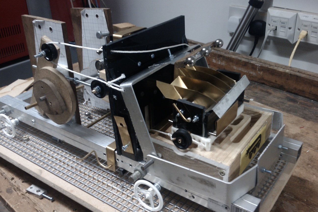
Had a couple of days to work on the Turing machine during November. It's now on its fourth revision lifter, this time there are two lifting arms, one which will stop at the top of the state box and the second containing the magnets which will continue on, so the magnets are separated from the ball bearings at the top. This seems much more reliable. It needs a longer movement on the string which lifts the arms up, so there's a pulley system to double the effect of the cam lever. I've also made some changes to the reversing mechanism, using a weight which is just slightly stably balanced so requiring a very small force to switch over to the other direction. This should be operating at the end of another day's work.
Sunday, 31 October 2010
Robot Hackday success

Nearly three years ago I wrote a little blog post about the MUTR micro rover kit which I'd just received then. I put together a basic rolling chassis then but then got distracted and didn't do anything more with it - until this opportunity came up.
Enter Robot Hackday, a day organised by MadLab and HacMan. People bring down old electronic junk and attempt to make automata out of them. We succeeded in making an army of wonderful robots, from scribblebots and shaking Altoids tins to furry tanks with glowing eyes. It was great to have a bit of banter with other hackers as we tried to get a robot ready within the day. One of the special guests this year was Tim Hunkin, a hero of mine since he presented The Secret Life of Machines many years ago. Tim's a really friendly chap and he spent ages helping me get my robot working.
In the photo is WrigglyBot, the robot I built on the day. I seem to have been photobombed by a robotic raptor. Someone else there (I forgot your name, sorry) named it as the front of the chassis ended up low enough to the ground to scrape chewing gum off the floor. The axles needed trimming to fit both gearboxes side-by-side, and then I drilled holes for the rear axle and redrilled the rear wheels so they were loose on the axle. There are three relays controlling the motor, one does the forward/reverse control for each motors, and the third is the main on/off control for both. As it stands, it can't run just one track at a time.
The relays are switched by the ever popular ULN2803 chip, and the whole caboodle is orchestrated by an mbed board. This is the first thing I've used an mbed for, and apart from a minor panic when MadLab's wifi left me without access to the mbed online compiler, it worked very nicely - certainly a lot less hassle to program than my usual microcontrollers. There's two batteries on board - the main 4x C cell runs everything, and would have run the mbed but it kept resetting when I switched the motors on, so I put in a separate 9v battery to run that.
The only problem is the clip-in worm gear sets. The worms tend to rise up when the gearbox is put under strain, and this will strip the gears if allowed to run for too long. Mine was still slipping despite lots of Araldite and wire holding the motors down. I think they need something to hold the worms down at the front.
Thanks to everyone at MadLab and HacMan, that was a great day out.
Sunday, 26 September 2010
September progress on the Turing machine

As of this evening, all the cams are working correctly and the main sequencing events (lift data, reset direction, drive) are working. The drive system is driving too far backwards, three grid spaces instead of two. The data lifter also requires far too much force to drive. Ideally, this could be counterbalanced by adding some lead weights, but there isn't a great deal of space to add anything right now.
The cams have been a lot more problematic than expected. Attaching a cam to a 5mm steel shaft requires some sort of flange which itself has to be secured to the shaft. I made several flanges out of aluminium which were meant to be fixed to the shaft by set screw, but in a lot of cases the thread failed before I could tighten the set screws enough to hold the cam. Filing flats on the shaft helps to some extent, but means the angle of the cam has to be decided then and there. When this machine is completed I think there might be quite a lot of subtle adjustment needed in the timing, so I'm reluctant to go filing or drilling the drive shaft right now.
Forward/reverse movement has been a cause for some concern. The 'punt' mechanism is working, but I'm not convinced it will be reliable in the long term. I also have plans for a more conventional forward/reverse gearbox and have a sprocket which will interface with the steel grid, thanks to Razorlabs.
We'll see how it goes.
Friday, 24 September 2010
A modder's guide to the 2010 BigTrak
Zeon Tech have started making a replica of the Big Trak (or bigtrak, or BigTrak, whichever you prefer) so I bought one to see how it'd work as a mobile robotics platform.
In the box you get the BigTrak, a manual and a pack of stickers to make it look like the illustration on the box. I think having stickers to apply yourself is great, so please continue with that, toy companies. As with the original, the centre wheels are driven and the front and rear axles are free. The front axle on this one allows some vertical movement, although it's not sprung. This presumably allows the machine to keep the weight on the middle wheels at all times, although it does mean it will rock back and forwards a little bit. The whole unit runs off 3 D cells, unlike it predecessor which needed a separate 9V battery, presumably to run the computer.
Underneath, there are plenty of screws to remove. The only difficult one is at the back, highlighted by the yellow arrow here. The plastic moulding on the back will come off with a bit of prodding, and you can see where the clips are if you remove the rest of the screws and open the case up a little. By pressing in in four places, it will come free. Don't bother removing any of the screws from the wheels or the grey drive unit underneath yet.
Once all the screws are removed, you can see inside. The ribbon cable goes up to the membrane keypad, which is unfortunately glued onto the case. However, the glue isn't strong and you can remove the keypad without damaging it. Wires at the front go to the 'photon beam' LED and speaker. One of the first mods you'll probably want to do is snip one of the speaker wires, although it will make programming the existing circuit board more tricky. The other wires go to the battery box and a tiny circuit board on top with the on/off switch and an IR LED; presumably the IR LED is for the trailer attachment, when that comes out. There's a lot of empty space inside the case, which is good news for modifying it.
Removing the ribbon cable and snipping the rest of the wires allows you to remove the drive unit. This is the least destructive way to get the drive unit out, as the controller board is soldered directly to the motors and can't be easily removed. The grey drive unit will now just drop out of the chassis. The circuit board is not particularly interesting, having two chips marked CE3962 which is the model number of BigTrak itself. There's a few discrete transistors on the underside of the board, which are probably the motor drivers. You might be able to modify this to operate the motor off TTL signals, but I'm not particularly interested in using it. 
So now the important bit. A few more screws removed and you can see the gearbox. I was expecting this new model to have skimped a bit on the components compared to the original, but this actually looks good - it still has encoders on the second set of gears, and it still has the magnetic clutch between the motors. This clutch keeps the motors in sync if you drive them at roughly the same speed, to improve your chances of driving in a straight line. The motors look small, but they didn't have any problems driving on thick carpet when I briefly tried them.
I'm pretty happy with this; my next plans are to install my IGEP board on it and connect up a couple of electronic speed controllers to run the motors. You can see the IGEP mounted (not connected to anything at the moment though) and the BigTrak with the (badly) applied stickers to the left. Amazon seem to the be the cheapest place to get them at the moment; I paid £32.48 for one including P&P through a reseller.
Saturday, 31 July 2010
Camping with dry ice
The next problem is transporting it - dry ice is constantly subliming into carbon dioxide gas, which will suffocate you in a closed container, and if you're driving you'll probably kill more people than yourself if that happens, so be really careful with it. This means you drive with all the windows open, and if it rains you get wet.
Once you've actually got the dry ice to a campsite, most of the difficult parts are done. You'll need another cool box, as you can't put food or drink straight into the dry ice container - it's about -86 centigrade in there. Put some heavy gloves on and transfer some dry ice into the bottom of a cool box, then cover that in a bit of cardboard and put your food or drinks on top of that. If bottles come into excessive contact with dry ice they will freeze and could shatter. If you need to cool something quickly, you can put another layer of cardboard on top of your beer and then shovel some dry ice on top of that. Now you can enjoy cold beer and wine well into the second and third day of the weekend and be the envy of the campsite. You'll probably only want to transfer a little bit of dry ice into a cool box at a time. I also found I could leave the cool block things you get for cool boxes in with the dry ice overnight without them exploding, but your milage may vary on that.
Lock the dry ice in your car when you don't need it, to prevent children and idiots playing with it - it will burn you if you touch it. Don't forget to give your car a few minutes airing with the doors open before getting in if the dry ice has been in there overnight. Don't put dry ice or any container containing it in your tent, for obvious reasons. Apart from that, the only problem will be disposing of it if you don't want to take the remainder home. Rather than just dumping it somewhere children or pets could burn themselves on it, you'll want to pour a lot of (ideally warm) water on it to disperse it. This could be quite a lot of water, so be prepared for a few trips to the tap.