No longer updated!

My blogspot site is no longer updated. Most of the posts here are archived at www.srimech.com along with new content.

Showing posts with label turingmachine. Show all posts

Friday, 8 June 2012

Exhibiting the Mk2 Turing machine

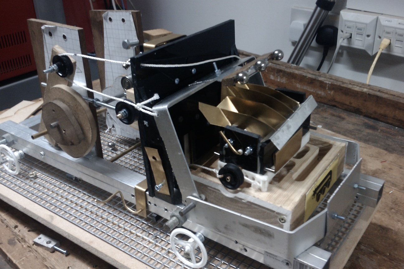
Here's a short video clip of the Mk2 Turing machine working at Derby Maker Faire. It took about 6 weeks from sending the plans off to RazorLab to having a working machine at the Handmade Digital exhibition in Manchester. There are still lots of handmade parts in the Turing machine, but having the majority of it laser-cut has made it much easier to construct.

There are also a lot of bugs in the design. One of the great things about the laser-cut design is that I can record these bugs as though they were software defects, which they are in many ways. The design for the machine is on github, at https://github.com/jmacarthur/millihertz/tree/master/scad/newbuild, although it may not be very intelligible at the moment. I really need to spend more time documenting the design.

Lots of people have said they like the shiny black laser-cut Turing machine, and others have said they prefer the scrappy style of the original. Personally I'd prefer to hand-make the final version out of solid brass, but that will be several iterations away.

Monday, 12 March 2012

Automating layout of laser-cut models


On the left is a rendering of part of my revised Turing machine. The important feature of this, for this post, is that it's a 3D object made up of flat cuboids 3mm thick, which means its parts can be cut out of a sheet of 3mm material by a laser cutter. It's designed (or perhaps written) in OpenSCAD.

Turning this into a 2D drawing to feed into a laser cutter is a manual process at the moment. The best way I've found to do it so far is to comment out all but one top level object at a time, then add an OpenSCAD projection primitive; compile, then export the resulting object as a DXF. This needs to be done for each part, with potentially different projection settings for each, and then the DXFs need to be manually combined.


This next picture is a rasterized SVG which was produced by a perl script I wrote to do this job automatically. The only post processing I've done is to move the top level objects around, as they end up on top of each other at the moment, and to increase the line width. As you can see, this is not perfect, as there are more cut lines there than there should be, but it is automatic. Another advantage of this method is that the produced diagram has true circles in it, rather than the polygonal approximations OpenSCAD produces. The script won't work on objects that are not within a thin plane; the model shown was already split into those objects and had the tabs added by hand. This script is just doing the job of rearranging objects into 2D form.

I am hoping to get the Clipper library involved next to do 2D unions and intersections necessary to produce useful laser cutter drawings. This library can also do outsetting, which will be useful to correct for the diameter of the cutting beam. (Inkscape can do outsetting too, but there is a bug in the current implementation relating to small lines at right angles.) For example, the tabs on the end of the thin bars shown above should be part of the same object. The script knows that these are part of a union, so should be union'ed in 2D to remove the line separating them.

There are of course restrictions in what this can produce; it's limited to orthogonal cubes, cylinders and polygons. Anything that produces an edge not perpendicular to the plane of the object will not work, but then it couldn't be produced by a normal laser cutter anyway. It shouldn't be limited to orthogonal planes - any orientation should work, although I've not tried it with non-orthogonals yet.

This perl script runs from the processed CSG output from OpenSCAD. This is thankfully very easy to parse. I used Parse::RecDescent to parse it. Then there are several passes of tagging elements in the tree and determining which shapes are positives and which are subtracted from the original solid; then a lot of matrix maths to identify top level objects which all fit into a 3mm thick plane segment and to project all its components into the same 2d plane. I hammered out the perl script in one day, and it's full of bugs and very badly written, so I'm not going to publish it right now. If anyone is interested in it, I'll tidy it up and open source it.

Wednesday, 16 March 2011

Turing Machine and Maker Faire


Here's a video I shot at Maker Faire UK 2011. I took the Turing machine along having just rebuilt it without testing, but it worked fine over the weekend after a little prodding and adjustment. I don't think everybody understood it, but everyone was positive about it and those that did understand what it did seemed very amused by it.

I didn't get much chance to have a look around the rest of Maker Faire, but it was an excellent event with some great minds getting together to create some great hacks (a video of Kinect controlled Tesla coils is doing the rounds at the moment).

Now that deadline's over, I can go back to the drawing board and start thinking about how to make a more reliable, precise version of this machine, or a more powerful machine which could actually demonstrate something useful - which would be better than explaining that this Turing machine would take months to add two numbers together.

Sunday, 6 March 2011

3D printed cellular automaton


Work on the Turing machine continues steadily, but in the meantime I have been working on a backup plan for Maker Faire. Since I have a fair amount of spare time when I can't get to London Hackspace to do stuff with drills and hacksaws, I started work on a 3D printable automaton. The result is in the video above. It's missing two levers since I plain forgot to include them in the order, and this prevents it from actually computing anything - but this video shows the robot reading input data and altering the output data. When the levers are in place, it'll only move some of the output data, thus doing something interesting.


The input data is the row of ball bearings on the bottom of this video. They're all ones for the purpose of this video. The output data starts off as all zeros, and gets set to ones as the machine moves along. In doing so, the machine calculates the (n+1)th row of a rule 110 cellular automaton (top row) based on the nth row (bottom row).


Although it's a lot simpler than my mechanical Turing machine, it does exactly the same function - but it needs replacing manually at the end of each row (generation). Moving in only one direction is a really big deal, and makes everything much simpler.

Both this and the Turing machine will be on display at Maker Faire UK next weekend in Newcastle (12th & 13th March). At least one of them will be working, but sadly I've had to forego steam power in order to run it indoors.

Saturday, 8 January 2011

Turing machine preview video


Here's some video I shot at London Hackspace last weekend. The machine isn't working properly, but this should show roughly what it'll look like when it does. There's some mild swearing on the soundtrack; mute it if that offends you.

I'll be back at the Hackspace tomorrow, making another lifter (5th revision!) which should make it easier to pick up ball bearings and allow more space for a better centering system when the ball bearings are returned to the track.

I've been accepted to Maker Faire UK in Newcastle in March - I'll have the machine running on a stand there with some more cellular automata stuff. See you there hopefully.

Friday, 31 December 2010

December machinery

The Turing machine ran three instructions in a row on Wednesday morning. I caught the 9am Tuesday train down to London Hackspace and worked through till 9am on Wednesday. The only problem remaining is getting the ball bearings to land reliably on the correct grid space. Direction change and movement are all solved problems now. I've added a gate released by an existing cam to stop the ball bearings exiting the machine too quickly, but the ball bearings often miss their correct grid spots.

This can be fixed by placing guards onto the grid, but I really want to avoid modifying the grid. Modifying an infinite tape requires infinite effort.

Wednesday, 24 November 2010

November Turing machine update


Had a couple of days to work on the Turing machine during November. It's now on its fourth revision lifter, this time there are two lifting arms, one which will stop at the top of the state box and the second containing the magnets which will continue on, so the magnets are separated from the ball bearings at the top. This seems much more reliable. It needs a longer movement on the string which lifts the arms up, so there's a pulley system to double the effect of the cam lever. I've also made some changes to the reversing mechanism, using a weight which is just slightly stably balanced so requiring a very small force to switch over to the other direction. This should be operating at the end of another day's work.

Sunday, 26 September 2010

September progress on the Turing machine


As of this evening, all the cams are working correctly and the main sequencing events (lift data, reset direction, drive) are working. The drive system is driving too far backwards, three grid spaces instead of two. The data lifter also requires far too much force to drive. Ideally, this could be counterbalanced by adding some lead weights, but there isn't a great deal of space to add anything right now.

The cams have been a lot more problematic than expected. Attaching a cam to a 5mm steel shaft requires some sort of flange which itself has to be secured to the shaft. I made several flanges out of aluminium which were meant to be fixed to the shaft by set screw, but in a lot of cases the thread failed before I could tighten the set screws enough to hold the cam. Filing flats on the shaft helps to some extent, but means the angle of the cam has to be decided then and there. When this machine is completed I think there might be quite a lot of subtle adjustment needed in the timing, so I'm reluctant to go filing or drilling the drive shaft right now.

Forward/reverse movement has been a cause for some concern. The 'punt' mechanism is working, but I'm not convinced it will be reliable in the long term. I also have plans for a more conventional forward/reverse gearbox and have a sprocket which will interface with the steel grid, thanks to Razorlabs.

We'll see how it goes.

Wednesday, 14 April 2010

Plans for a mechanical Turing machine


This is a project I've been planning for many years. It's a design for a fully mechanical universal Turing machine. My self-imposed constraints are to use no electronic or even electrical components, to be driven by a single rotating input shaft, and to be constructable with simple hand tools, without relying on high precision parts.

Trying to design something like this is an interesting challenge, and something I've found I can work on entirely in my head when I'm stuck somewhere with some spare time and not even as much as a sheet of paper to draw ideas on. Some of you might like to stop reading here and try and figure out a design yourselves before this plan taints you.

I had most of the conceptual design finished at the start of this year, and it's taken until now to get a fully specified model made up in OpenSCAD. I think this is now ready to manufacture.

One of the most difficult initial problems is how to store a reasonable amount of data, such as the tape for a Turing machine without having to manufacture a large number of custom parts. My design uses ball bearings on a sheet of pattern perforated metal as the tape. The position of balls on the grid is the data, and the machine moves back and forward on the grid. To be strictly universal, the perforated metal sheet needs to be infinitely long. I haven't carefully examined the sheet RS have sent me but will assume it to be infinite for the time being.

I'll now try to describe how the rest of the machine works, which is pretty difficult and I don't think this will be immediately clear. I hope to have a working prototype soon which should make its operation clearer.

This schematic diagram shows the main components of the machine.

The next component after the grid and set of ball bearings is a lifting arm or raiser (red) which picks up the 'input symbol' under the read head and lifts it to the top of a block of channels not unlike a marble alley. The run needs to contain some state which will direct the ball down different channels, and needs levers which will update the state for the next ball, and set the direction the machine will move. It also needs to direct the ball back to a new position on the perforated sheet to 'write' the new symbol.

First in the run is the 'state box' (cyan) which diverts the ball down down one of two paths depending on the position of the gate. The position of the gate is the state of the Turing machine. Paddles on the gate also turn the gate as the ball falls, setting the new state of the machine. The output of this box is a ball in one of ten positions, representing the combinations of five input symbols and two initial states.

The next part is the 'direction box' (green) which has levers in some of the ten paths which will alter the direction of the Turing machine later on. If a lever is hit, the machine moves left, and if not, it moves right. The actual movement isn't carried out in this phase, as the falling ball won't have nearly enough power to move the whole machine, but it sets state which will be picked up later.

After falling through the state box, the ball falls into the 'maze' (orange) which maps the ten input positions into one of five output positions, which is the output symbol for the machine. A set of gutters under the maze will return the ball to the grid in its new output symbol position.

Behind the marble alley, there's a tower which performs the movement for the whole machine. A cam (blue) drives a set of three levers (brown) which move the machine. The bottom lever can be easily deflected from one side to the other while it's raised; this is done by a linkage from the direction box. The cam drives the levers downwards, where they engage with the grid and push the whole machine forward or backward two grid spaces.

There are other cams to run the raiser and to reset the direction box each cycle.

The whole machine rides on wheels which ride on top of the grid. Using round wheels on a square grid will provide a small amount of alignment so the machine doesn't drift away from the positions of the balls.

This machine is a 5-symbol, 2-state Turing machine. The configuration comes from Stephen Wolfram's "A New Kind Of Science", which shows this to be a universal machine. While it's relatively simple, it's also ridiculously inefficient and could not be used as a practical computing device. It's just meant as a demonstration of how simple a universal computer could be.

Sunday, 11 April 2010

Fab Lab success


This is a picture of two attempts at making a machine component. I'll explain what it actually does later, but this is mainly a post about how I made them.

On the right is my first attempt, cut by hand with a Dremel with a router accessory. As you can see, it's pretty rough, but it just about works - you can drop a ball bearing into one of the slots and it will roll down to one of the exit holes in the base. Sometimes they'll stick, so it needs a bit more work yet.

On the left is a CNC milled block which I was able to get made due to the opening of Fab Lab Manchester. I mentioned this a while ago when they made their press release, and they've just opened so I went along on Saturday. It's an amazing place and free to use on Fridays and Saturdays so long as you don't mind sharing the details of your project. This was cut using their enormous ShopBot CNC vertical mill.

I'd never got on well with 3D modelling programs and tended to use POVRay to model projects since I'm used to working with code rather than WYSIWYG editors. At Maker Faire UK this year I discovered OpenSCAD which is in some ways similar to POVRay - it takes a text scene description file and produces a 3D representation which can then be exported as an STL file - a format which milling machines and 3D printing machines can understand. The maze shown was just a piece of text in an editor on Thursday night, and by Saturday afternoon I'd been able to turn it into a physical object. For an amateur mechanical engineer like me, this really changes the game and allows a huge number of ideas that I'd never otherwise be able to realise. I'm very grateful to Fab Lab and especially Hayden who spent most of his afternoon showing me how to set up the mill.


If you're still interested in what it does, the diagram to the left might make it clearer. The idea is to drop a ball bearing into one of the central slots, marked by the yellow squares. The two columns represent two states of a state machine, and the five rows are the five different input symbols. Based on the state and input symbol, the ball bearing rolls down to one of five output holes. The vertical position of the output hole is the output symbol. In short, this is part of the control logic for a 5-symbol, 2-state universal Turing machine - the Wikipedia article may help explain this if you're not familiar with them.